Ceiling Fan Remote Hacking
In this post I will be covering how I modified the “owenb321/hampton-bay-fan-mqtt” to work with some “Home Decorations #1001 415 438” fans I had installed a while back. The fans make use of a pretty standard remote control “model number: TX028C-S”, however the only repository I found did not produce compatible codes for the fans prompting me to create this offshoot of the repo.
I will cover the basics. I went through reverse engineering the commands sent to \ from the fans along with how I was able to recreate them and send it back to the fans successfully. This was a fun journey where I needed to do a lot of binary maths \ manipulation to get everything working.
You can skip all of this and just get the source code here if you would like.
Required Hardware and Setup
In order to follow along you will need to have access to the following hardware:
- ESP8266 (or compatible chipset) - I am using a Wemos D1 Mini
- CC1101 Wireless Transceiver - I am using this one.
- Some wire to make the connections between the
ESPxxxandCC1101 - Arduino IDE - used to build and upload the code
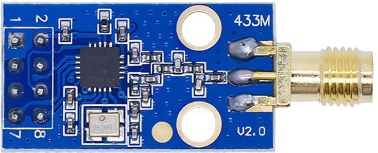
Module Wiring
Depending on your CC1101 module, your wiring may be different, please ensure that you check your modules specific wiring before continuing.
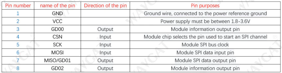
The module that I selected has the following pinout:
Corresponding to the physical PCB board layout:
Based on the wiring diagram here I would need to make the following connections.
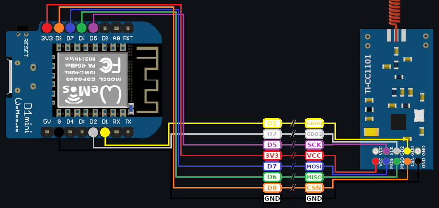
| CP1101 | ESP8266 | Mode | Notes |
|---|---|---|---|
| GD00 | D1 | Output | Module Info output pin |
| GD02 | D2 | Output | Module information output pin |
| SCK | D5 | Input | SPI bus clock |
| VCC | 3V3 | - | Power supply must be between 1.8-3.6v |
| MOSI | D7 | Input | SPI data input pin |
| MISO | D6 | Output | SPI data output pin |
| CSN | D8 | Input | Chip select pin |
| GND | GND | - | Ground wire |
Arduino Libraries
The following libraries are required to compile the project:
For simplicity and to ensure that your build works these have been included in my repository under the libs directory (here).
Project Usage
Usage is pretty straight forward, and can be done by following these steps:
- Clone the repository locally
- Open
./homefans/homefans.ino - Make any required changes to
./homefans/config.hWIFI_*to configure the WiFi connectionMQTT_*to configure your MQTT connectionRF_*to change any required RF related settings
- Ensure your device is connected and available via a COM port
- Compile and upload the sketch
Reverse Engineering
This section covers (at a high-level) how I was able to reverse engineer the remote codes and modify the existing project to meet my needs.
Capturing Codes
The first thing I needed to do was to capture any codes being sent by the remotes, this was as simple as modifying the sketch to log out the values captured by RCSwitch:
1
2
3
value = mySwitch.getReceivedValue();
prot = mySwitch.getReceivedProtocol();
bits = mySwitch.getReceivedBitlength();
Resulting in values like the table below:
| Protocol | Bits | Value | Dip Pos | Action |
|---|---|---|---|---|
| 11 | 24 | 16543350 | 0001 | Fan Speed 1 |
| 11 | 24 | 16542838 | 0011 | Fan Speed 1 |
| 11 | 24 | 16541814 | 0111 | Fan Speed 1 |
Decoding the bits
At first glance this may all seem like nonsense - how does “16543350” turn on a specific fan to a specific speed? To answer that we first need to convert these values to their binary representation, this resulted in the following 24 bits:
| Int | A | B | C | D | E | F |
| 16543350 | 1111 | 1100 | 0110 | 1110 | 0111 | 0110 |
| 16542838 | 1111 | 1100 | 0110 | 1100 | 0111 | 0110 |
| 16542838 | 1111 | 1100 | 0110 | 1000 | 0111 | 0110 |
Note: This table is referenced a LOT below
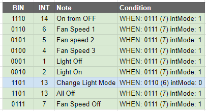
This process was repeated for each possible command on the remote and compared once done, during my comparison the following stood out:
- Columns
A,B, andCare static regardless of theDIP switchpositions- Perhaps this is a carrier code \ id \ etc
- Column
Dis the positions of theDIP switches(only inverted - 0001 -> 1110) - Column
Eis generally0111unless using light effect commands, in that case it is0110 - Column
Fis the actual command to execute (i.e. fan speed, light on, etc.)
With this information I was able to piece together the following truth table:
Encoding Codes
The process of re-encoding the remote codes is as simple as reversing this process (covered later on), at least this is some good news - we can work with this.
Arduino Sketch
Implementing this in the original Arduino sketch was a bit of a hack on my end, however with some persistence I was able to do it.
Decoding RF Input
When a RF code is detected we need to decode it, this process begins with reading the received value:
1
value = mySwitch.getReceivedValue();
Followed by manipulating the value into somethin we can work with:
1
2
3
int subtractedValue = value - 0b111111000110000000000000;
int truncatedValue  = subtractedValue >> 8;
int id              = truncatedValue ^0b1111;
- First we can remove the common
1111 1100 0110using a subtraction - We can bit-shift right by 8 places to remove the mode (column
E) and command (columnF) to be left with the inverted DIP switch values - We can then invert the bits using an XOR command to get the actual DIP switch positions
Once done we need to check that the RF protocol and bits are what we are expecting before we can continue.
1
if( prot == 11 && bits == 24 ) { }
Once confirmed we can start unpacking the Mode from the received value using the subtraction result.
1
int cmdMode = ((subtractedValue & 0b000011110000) >> 4) % 6;
- I decided to use an AND operation to zero out all useless bits - effectively performing a soft-truncation of the left most bits
- We binary-shift right 4 bits to get the command as the left most bits are now
0000 - This results in either an int value of 6 or 7
- Using modulus we can convert that to a 1 or 0
1= normal commands0= light temperature related commands
We can finally turn our attention to extracting the actual command from the received code, this is done like so:
1
int command = subtractedValue & 0b000000001111;
- Using an AND operation we can zero out columns
DandE - The remaining value is the command to execute
- You can see an example of commands in the reverse engineering section above
All that is left to do is respond to the received code.
Encoding Codes
Encoding outgoing RF codes is basically reversing the process used to decode them, and looks like this:
1
2
3
4
int baseCommand = 0b111111000110000000000000;
int fanIdDips   = (fanId ^ 0b1111) << 8;
int commandInt  = 0b01110000;
int command     = 0b0000;
- Start with defining the static parts of the remote code (columns
A,B, andC)- i.e.
0b111111000110000000000000
- i.e.
- Invert the fanID to recreate (column
D)- Bit shift this left by 8 to allow for insertion of column
E, andF
- Bit shift this left by 8 to allow for insertion of column
- Define the static commandInt value
- In the future this would change if I add support for the light mode
- Finally I define a placeholder commandInt to populate with the outgoing command
Next I switch based on the received MQTT attribute (attr) and command (payload).
Once set, the final command is generated by combining all the parts (basically adding the int values together) to create the expected int of 16543350.
1
int finalCommand = baseCommand + fanIdDips + commandInt + command;
This value is then transmitted using the same protocol and bit length used to receive it, this results in the fan thinking the command came from the remote.
If your fans do not respond to the command you should try changing the frequency value
RF_FREQUENCY- I wasted a good 45 min with this one!
Everything Else
The rest of the code is pretty much in line with the source repository.
I have no doubtably introduced some new BUGS in the code-base and will need to tackle them when discovered!
Home Assistant
Once you have your ESP device deployed, adding it to Home Assistant is as simple as adding an MQTT fan and light entry per fan you wish to control.
MQTT Fan Configuration
In this case I am creating an entry for my remote with a DIP switch position of 0001:
1
2
3
4
5
6
7
8
9
10
11
12
13
14
15
mqtt:
  fan:
    - name: "Master Bedroom Fan"
      state_topic: "home/fans/0001/on/state"
      command_topic: "home/fans/0001/on/set"
      preset_mode_state_topic: "home/fans/0001/speed/state"
      preset_mode_command_topic: "home/fans/0001/speed/set"
      preset_modes:
        - "off"
        - "low"
        - "medium"
        - "high"
      qos: 0
      payload_on: "on"
      payload_off: "off"
MQTT Light Configuration
In this case I am creating an entry for my remote with a DIP switch position of 0001:
1
2
3
4
5
6
7
8
9
mqtt:
  light:
    - name: "Master Bedroom Fan Light"
      state_topic: "home/fans/0001/light/state"
      command_topic: "home/fans/0001/light/set"
      qos: 0
      payload_on: "on"
      payload_off: "off"
      optimistic: false
Entities
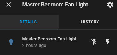
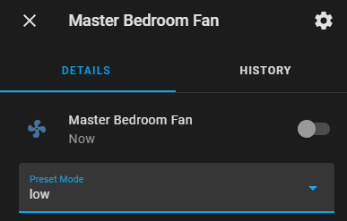
Once restarted you should see all your fan and light entities in Home Assistant.
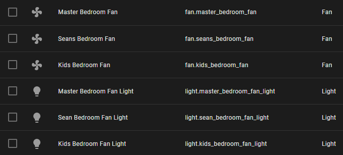
As expected the light entries work as per normal:
Along with the fan entities:
Dashboard Configuration
I am personally using the following configuration to control my fans in Home Assistant:
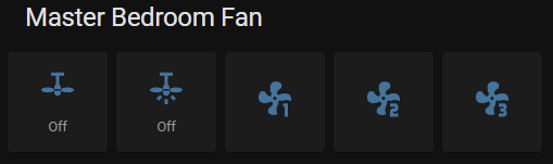
Backed by the following configuration:
1
2
3
4
5
6
7
8
9
10
11
12
13
14
15
16
17
18
19
20
21
22
23
24
25
26
27
28
29
30
31
32
33
34
35
36
37
38
39
40
41
42
43
44
45
46
47
48
49
50
51
52
53
54
55
56
57
58
59
60
61
62
63
64
65
66
67
68
69
70
71
72
73
74
75
square: true
columns: 5
title: Master Bedroom Fan
type: grid
cards:
  - show_name: false
    show_icon: true
    type: button
    tap_action:
      action: call-service
      service: fan.toggle
      data: {}
      target:
        entity_id: fan.master_bedroom_fan
    entity: switch.master_bedroom
    icon: mdi:ceiling-fan
    show_state: true
    hold_action:
      action: none
  - show_name: false
    show_icon: true
    type: button
    tap_action:
      action: call-service
      service: light.toggle
      data: {}
      target:
        entity_id: light.master_bedroom_fan_light
    entity: light.master_bedroom_fan_light
    icon: mdi:ceiling-fan-light
    hold_action:
      action: none
    show_state: true
  - show_name: true
    show_icon: true
    type: button
    tap_action:
      action: call-service
      service: fan.set_preset_mode
      data:
        preset_mode: low
      target:
        entity_id: fan.master_bedroom_fan
    entity: ''
    icon: mdi:fan-speed-1
    hold_action:
      action: none
  - show_name: true
    show_icon: true
    type: button
    tap_action:
      action: call-service
      service: fan.set_preset_mode
      data:
        preset_mode: medium
      target:
        entity_id: fan.master_bedroom_fan
    entity: ''
    icon: mdi:fan-speed-2
    hold_action:
      action: none
  - show_name: true
    show_icon: true
    type: button
    tap_action:
      action: call-service
      service: fan.set_preset_mode
      data:
        preset_mode: high
      target:
        entity_id: fan.master_bedroom_fan
    entity: ''
    icon: mdi:fan-speed-3
    hold_action:
      action: none
This can be repeated for each fan you wish to control.
Proto-boarding
Finally I tried to neaten everything up by placing all the components on a proto-board, and I will soon be designing and printing a case for the final project.
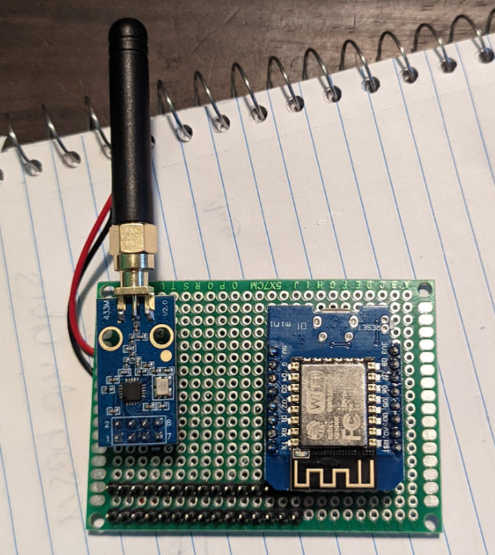 Looking good from the front
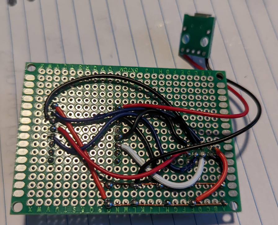 The wiring at the back is not amazing
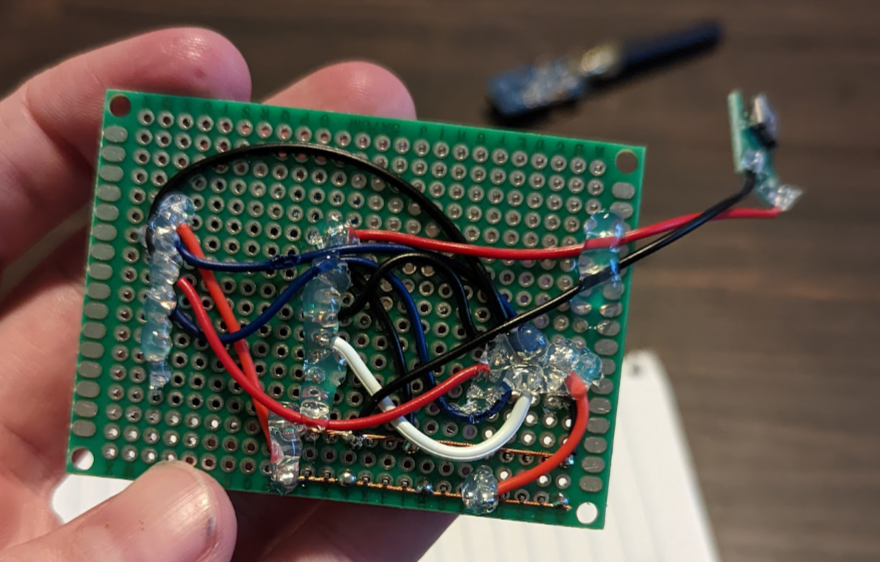 don’t forget the hot glue
In Closing
This project was a good brain teaser and forced me to re-learn basic comp-sci principles like bitwise operations and binary maths.
I would like to give a shout out to Ben Owen for the original work done here as it saved me a lot of time along with providing me with a good starting place.
Please feel free to clone my repo, make changes, submit pull requests as this is no way complete - yet!
Happy hacking.