Programming an ATTiny85 with an Arduino Uno
I recently received a couple of ATTINY85 micro controllers from BangGood in hopes of shrinking down some of my Arduino projects in the future. Initially I was a bit stumped on how to “flash (program)” these chips, and the USB adapter I bought for the process was DOA. After an hour or so on Google I had my first “Blink” sketch up and running on my ATTiny! I decided to make this post as a reminder to myself and to help others who may want to get up and running quickly with their own ATTiny85.
Adding ATTiny Support to Arduino IDE
The first thing we need to do is add support for the ATTiny microprocessor family to the Arduino IDE. Now all the video tutorials I found online seemed to be pre-2015, and all of them stated that support was lacking for the microprocessor, however it seems that this is not the case anymore! Adding support seems to be straight forward.
Open the Arduino IDE and navigate to File -> Preferences. In the dialog that appears locate the Additional Boards Manager URLs field and set its value to the following.
1
https://raw.githubusercontent.com/damellis/attiny/ide-1.6.x-boards-manager/package_damellis_attiny_index.json
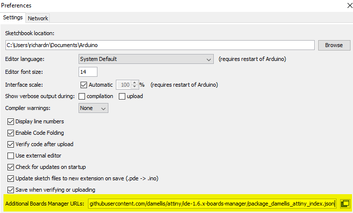
Once done, close the preferences dialog and launch the Board Manager dialog (Tools -> Board: xxx -> Boards Manager) and give it some time to load the new boards from the URL provided earlier. Once done you should now be able to search for ATTiny in the Board Manager window.
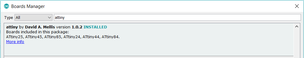
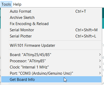
Pick (attiny by David A. Melis) from the search results and click install, once done you can close the Boards Manager. Verify that the board was installed successfully via Tools -> Board…
ATTiny85 Flashing Components
Next, we will need a couple of components in order to flash out ATTiny85, they can be seen below.
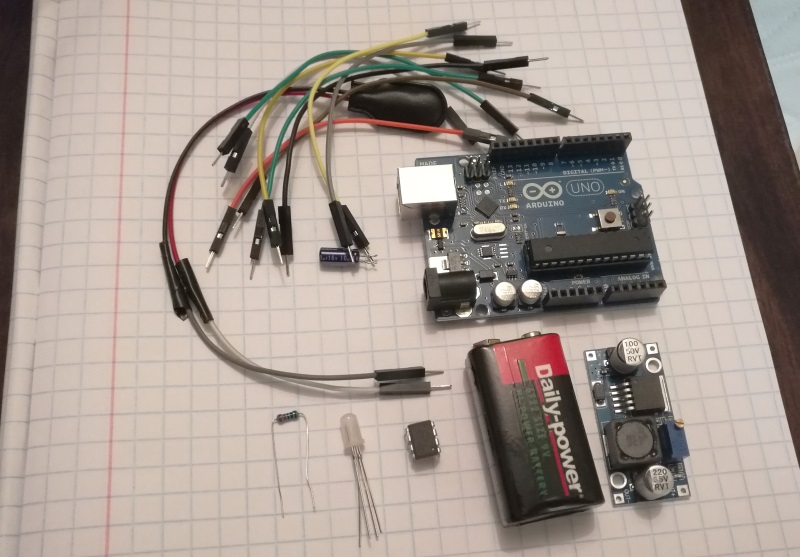
The component list is as follows:
- ATTiny85 microprocessor
- Jump wires (and a breadboard)
- Arduino UNO (although other variants should work)
- 20 uF capacitor (used for the UNO, may be optional if using another board)
- LED - for running test code (I am making use of a RGB LED)
- Resistor for the LED (
150 ohmshould be fine) (*) - 9v battery, clip and regulator (used to provide 5v to the ATTiny once flashed) (
**)
(*) Your resistor value may differ from mine and that’s alright, anything around the 130 ohm mark should be fine - I used this website to work out the appropriate resistor using a source voltage of 5v, LED forward voltage of 2v and draw of 20 mAh.
(**) You can use any 5v power source to power your ATTiny, I just happened to have a regulator available.
That pretty much covers all the components that you will need, let’s move on.
Prepping the Arduino UNO
Next up we will need to flash the ArduinoISP sketch to your master Arduino (in my case the UNO). Before flashing the sketch please ensure that you have selected the correct board and port then hit the upload button.
Provided there were no errors writing to your Arduino you can mark this step as completed.
Connecting the ATTiny to your UNO
The next logical step would be to wire up the ATTiny to the newly created Arduino ISP, but before we do that let’s take some time to get familiar with the pinout of the ATTiny.
ATTiny pinout
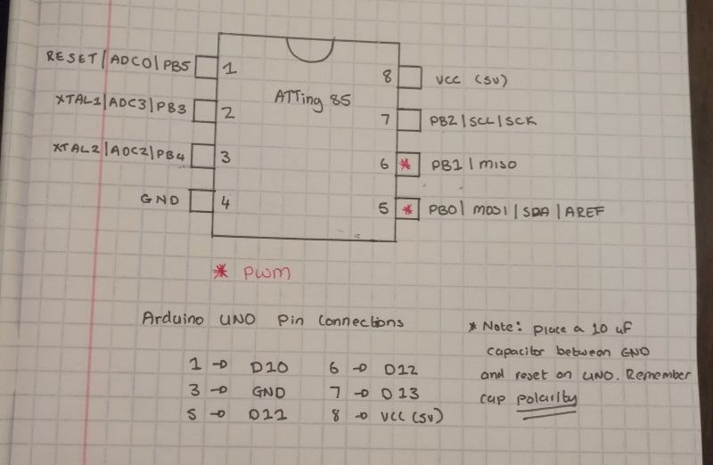
Below you can see my cheat sheet for the ATTiny85 microprocessor, the pinout differs based on the version of the microprocessor you choose, so please double check the spec sheet if you are using a different variant of the ATTiny.
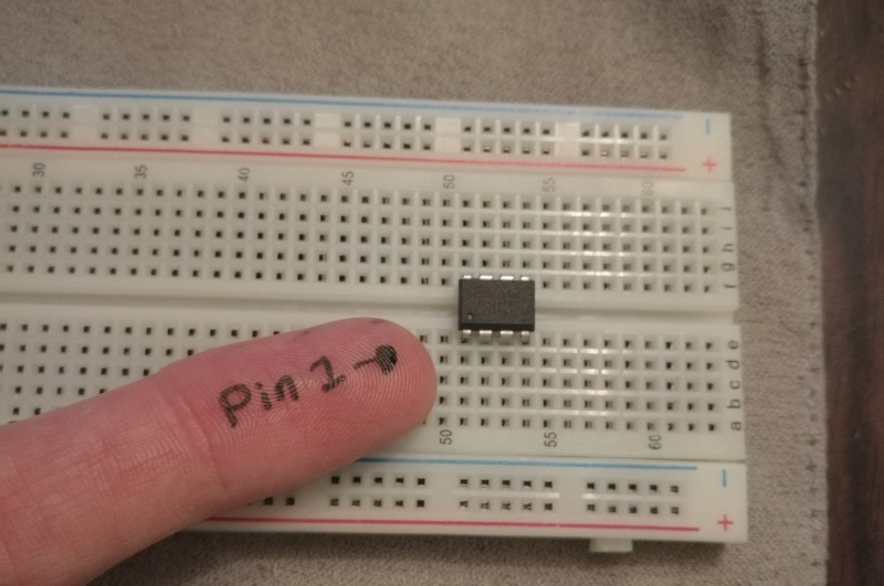
Finding pin1
pin1 can either be marked with a small dot close to the pin (as in my case), or by a small groove carved into the top of the chip (see above picture). If your chip has a groove carved in it (opposed to the marker dot) pin-1 is usually on the left-hand side of the groove.
Powering the ATTiny for programming
Next, we will need to provide power to the ATTiny while we are flashing it. From my cheat sheet we know that the following pins provide power to the ATTiny.
1
2
4 ............ GND
8 ............ VCC (5v)
Thankfully the Arduino UNO provides us a 5v and GND pin we can use to power our ATTiny. We can provide power to the chip directly from the 5v source on the UNO via our breadboard, as shown below.
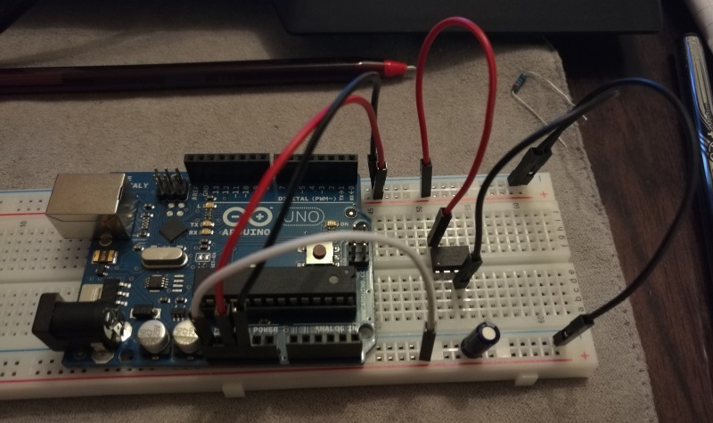
Here I am doing the following:
- Jumping the 5v and GND pins to the breadboard power rail
- Jumping 5v to pin8
- Jumping GND to pin4
- Bridging the (-) rail from the top of the breadboard to the bottom (-) rail (for the capacitor)
- Feeding the (+) output of the capacitor to the RESET pin of the UNO (used for flashing)
NOTE: when wiring in the capacitor be sure that you get the polarity right as electrolytic caps don’t like being wired in reverse polarity (ensure that the (-)pin goes to GND).
Connecting ATTiny data pins
Now all that’s left here is to connect the appropriate pins from the ATTiny to our Arduino for programming. We will use the following pinout.
1
2
3
4
5
6
1 .............. D10
3 .............. GND
5 .............. D11
6 .............. D12
7 .............. D13
8 .............. VCC (5v)
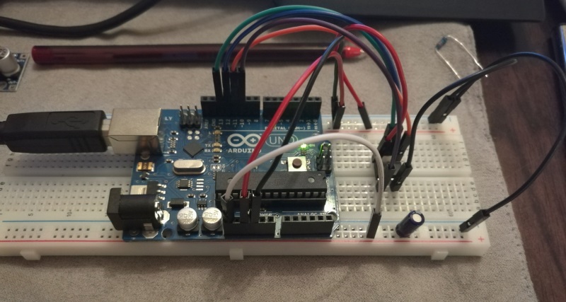
We now have all the required pins connected, and are good to flash/burn our first sketch.
Burning our first sketch
Based on all the various sources I collected my information from the process of burning your first sketch to ATTiny chips is:
- (First time only) Burn the bootloader to the ATTiny
- (Every time) Burn your sketch
Configuring Arduino IDE
The first thing we need to do is ensure that we have our Arduino IDE configured correctly before continuing.
Ensure that you have the correct Board, Processor, Clock Speed and Portselected. You do not want to target your UNO at this point!
Burning the bootloader
To burn the bootloader to your ATTiny, please ensure that you have the correct Board, Processor, Clock Speed and Port selected before doing anything else!
Once you have the correct values selected all you need to do is go Tools -> Burn bootloader and watch the output console for any errors.
Everything should go through fine, if not this would be a good time to double check all your connections to the ATTiny chip and ensure that you have targeted the correct board.
Updated blink sketch
Now the fun bit, an updated “Blink” sketch. We are going to upload the following code to the ATTiny.
1
2
3
4
5
6
7
8
9
10
11
12
13
14
15
16
17
18
19
20
21
22
void setup() {
  pinMode(PB1, OUTPUT);
  pinMode(PB2, OUTPUT);
  pinMode(PB3, OUTPUT);
}

void loop() {
  digitalWrite(PB1, HIGH);
  delay(500);
  digitalWrite(PB1, LOW);
  delay(500);

  digitalWrite(PB2, HIGH);
  delay(500);
  digitalWrite(PB2, LOW);
  delay(500);

  digitalWrite(PB3, HIGH);
  delay(500);
  digitalWrite(PB3, LOW);
  delay(500);
}
This is a simple blink program with the following differences:
- Instead of using the D1 / A1 pin assignments I am making use of PB1… as per my cheat sheet above
- I am cycling through 3 colors on an RGB LED
- I am not making use of any Serial calls (not available AFAIK).
Uploading the sketch
With your UNO connected to your computer (and making sure your targets are correct), you can just paste the code above and click upload. You should see the following output displayed in the Arduino IDE.
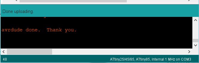
We have successfully flashed our sample code to the ATTiny. Let’s disconnect all unneeded jump wires from the breadboard.
- You can remove D10, D11, D12, D13
- If you would like to use the arduino to power the ATTiny leave GND and 5vconnected, otherwise remove them too.
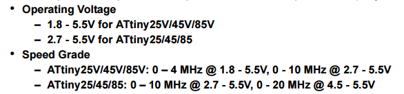
Running without Arduino
The last thing we need to do is get rid of that bulky Arduino UNO board and power our project through some other mechanism. Looking at the data sheet it would seem that the ATTiny85 can be powered with anything from 1.8v - 5.5v.
From the cheat sheet above we know that the ATTiny draws power on pins 4and 8.
1
2
4 ............ GND
8 ............ VCC (5v)
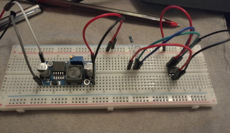
So, all we need to do is provide our chip with a voltage higher than 1.8v but less than 5.5v and we should be good to go. As you can see from the pictures below I went with a variable power supply with an output voltage set to 5.07v, connected VCC to 8 and GND to 4 along with the required jumpers & resistor to power the RGB LED.
Another picture looking down onto the breadboard.
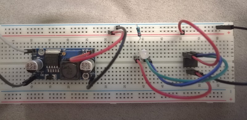
That’s all we need to do, our ATTiny now has our sketch loaded to it along with a stable power source, the last thing left to do is power it up and see what happens.
Comments powered by Disqus.