Lounge Clock (v 1.0)
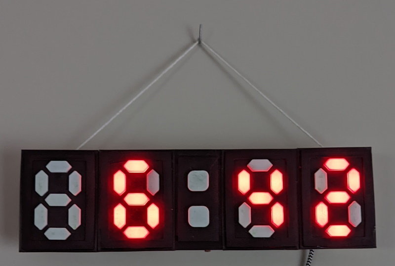
In this post I will cover how I built my lounge clock using ESPHome, Home Assistant, MQTT and a whole lot of other technologies, I think that the end result looks pretty good for my first attempt:
Bill of Material
The following tools \ materials are required should you want to make your own:
- 3D Printer - or a 3D printing service near you
- 4x 7-Segment display PCB’s - more information below
- Piece of wood to mount the clock on
- ESP8266 - preferably the Wemos D1 Mini
- Some wires to connect everything together
- 2 Part Epoxy - I find it works best with PLA
- Hot glue gun (and glue)
- DHT11
- 2x 10K resistors
- 1x LDR
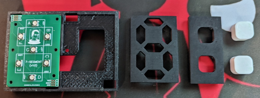
Custom PCB
Using Easy EDA I was able to come up with the following circuit board:
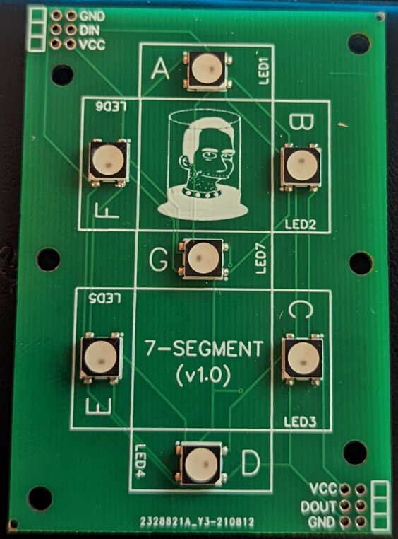
It’s a pretty simple board that makes use of some WS2812b SMD LEDS wired in the traditional 7-segment pattern:
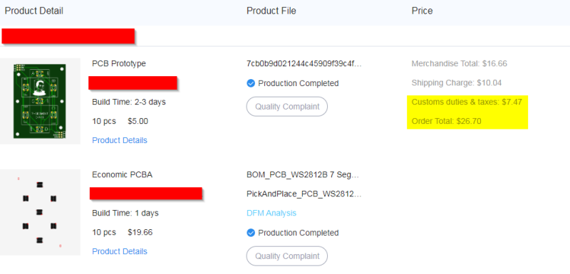
For fabrication I made use of JLCPCB and their pick and place service, all in 10 boards assembled cost me $27.00 (not too bad!).
I have made the Gerber files available here if you would like to make your own.
3D Printing
There is a LOT of 3D printing required for this project, namely:
- 2x Double 7-Segment risers - used to group 2 segments together
- (Optional) 1x Double 7-Segment risers template - used for drilling holes
- 4x 7-Segment covers - in black if possible for the best results
- 28x Segments - I would print more as they break easily
- 1x Dots holder - used to hold 2 additional
WS2812 LEDs - 1x Dots cover - in black if possible for the best results
- 2x Dots segments - plus a couple of spares
- 2x Double 7-Segment covers - my attempt at cleaning up the mess at the end :)
The assembly is pretty straight forward (like Lego for adults) and I left enough space to route all the required wires through the risers to give the clock a neater look - although I do not know what happened to mine!
I would put aside ~18 hours for all the printing to be completed (depending on your printing profile).
Assembly
Unfortunately I did not take any pictures of the assembly process, however it is pretty easy.
Each 7-Segment board has a DIN (Digital In) and DOUT (Digital Out) solder point, which need to be daisy chained from one board to another.
On the PCB all the GND points are all connected together, along with the VCC points to make routing power a lot easier. When connecting the boards you just need to follow this pattern if you are using the source code I provide.
1
DIN -> [7-Seg] -> [7-Seg] -> [7-Seg] -> [7-Seg] -> [.] -> [.]
Where the following is true:
7-Seg- represents a 7-Segment PCB[.]- represents a single WS2812x LED
The entire assemby should be mounted onto a backing board (using the stencil to make the appropriate holes), and the additional components should be connected to the ESP8266 similar to the diagram below:
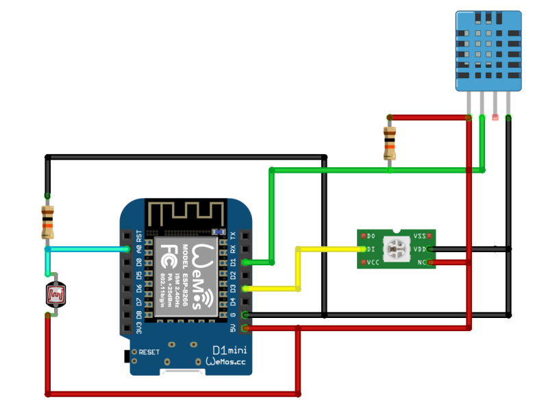 NOTE the single LED represents all the PCBs
1
2
3
D3       WS2812B        Lights
D1       DHT11          Temperature
A0       ADC - LDR      Brightness
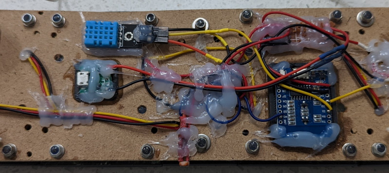
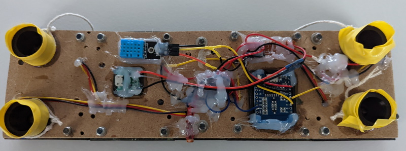
Like most DIY projects it may not be pretty, but it works!
FYI: the yellow tape on the spacers are to stop the plastic rubbing on my walls
Source Code
The source code use for my clock is an adaptation of the code found here and I take no credit for the original code, only the modifications to it - thestovedoc deserves the credit!
The modified code can be found here and requires that you either replace the !secret ... placeholders, or inline them into the code before uploading it to the ESP8266.
Segment Values
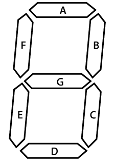
As mentioned above the 7-Segment PCB’s follow the standard layout (A, B, C, D, E, F, G) to make defining numbers a lot easier.
Below is the number range used in this project as an example:
1
2
3
4
5
6
7
8
9
10
11
12
13
14
int digitsLeds[11][ledsInDigitCount] = {
// A B C D E F G
  {1,1,1,1,1,1,0}, // 0
  {0,1,1,0,0,0,0}, // 1
  {1,1,0,1,1,0,1}, // 2
  {1,1,1,1,0,0,1}, // 3
  {0,1,1,0,0,1,1}, // 4
  {1,0,1,1,0,1,1}, // 5
  {1,0,1,1,1,1,1}, // 6
  {1,1,1,0,0,0,0}, // 7
  {1,1,1,1,1,1,1}, // 8
  {1,1,1,1,0,1,1}, // 9
  {0,0,0,0,0,0,0}, // 10 -> ALL_OFF!
};
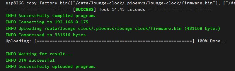
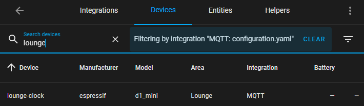
Home Assistant Setup
Setting everything up in Home Assistant is pretty simple once you have flashed the firmware to your ESP8266 using the ESPHome:
Card Control
To allow for easier control of the clock I added the following card to my dashboard:
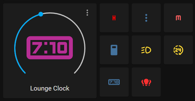 It’s not that pretty, but it gets the job done!
Working left to right:
Clock Control- allows for quick control of the clocks brightnessH- (hours) short press to toggle, long press to adjust:- (dots) short press to toggle, long press to adjustM- (minutes) short press to toggle, long press to adjustLeading 0- used to toggle the leading0(24 hour \ 12 hour format)Blinking- used to toggle the blinking of the:as it can be annoying when watching TV12\24- toggles between 12 and 24 hour time formatClock Mode- quickly enables the clock mode - there are other effects on the clockLights- group of all the lights making up the lounge clock
The backing code is shown below:
1
2
3
4
5
6
7
8
9
10
11
12
13
14
15
16
17
18
19
20
21
22
23
24
25
26
27
28
29
30
31
32
33
34
35
36
37
38
39
40
41
42
43
44
45
46
47
48
49
50
51
52
53
54
55
56
57
58
59
60
61
62
63
64
65
66
67
68
69
70
71
72
73
74
75
76
77
78
79
80
81
82
83
84
85
86
87
88
89
type: horizontal-stack
cards:
  - type: light
    entity: light.lounge_clock
  - square: true
    columns: 3
    type: grid
    cards:
      - show_name: false
        show_icon: true
        type: button
        tap_action:
          action: toggle
        entity: light.lounge_hours_lights
        hold_action:
          action: more-info
        name: HH
        icon: mdi:alpha-h
        show_state: false
      - show_name: false
        show_icon: true
        type: button
        tap_action:
          action: toggle
        entity: light.lounge_dots_lights
        hold_action:
          action: more-info
        name: ':'
        show_state: false
      - show_name: false
        show_icon: true
        type: button
        tap_action:
          action: toggle
        entity: light.lounge_minutes_lights
        hold_action:
          action: more-info
        name: MM
        icon: mdi:alpha-m
        show_state: false
      - show_name: false
        show_icon: true
        type: button
        tap_action:
          action: toggle
        entity: switch.lounge_leading_zero
        name: Zero
        icon: ''
        show_state: false
      - show_name: false
        show_icon: true
        type: button
        tap_action:
          action: toggle
        entity: switch.lounge_dots_blink
        name: Blink
        icon: mdi:car-light-dimmed
        show_state: false
      - show_name: false
        show_icon: true
        type: button
        tap_action:
          action: toggle
        entity: switch.lounge_24_hour_format
        name: '24'
        icon: mdi:hours-24
        show_state: false
      - show_name: false
        show_icon: true
        type: button
        tap_action:
          action: call-service
          service: light.turn_on
          service_data:
            effect: Time Effect
          target:
            entity_id: light.lounge_clock
        entity: ''
        icon: mdi:clock-digital
        hold_action:
          action: none
      - show_name: false
        show_icon: true
        type: button
        tap_action:
          action: more-info
        entity: light.lounge_clock_all_lights
        hold_action:
          action: none
Collected Data
In addition to displaying the time, the clock also collects and submits the following data:
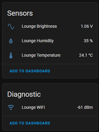
Brightness- handled by the LDR - measured in voltage (HIGHER= brighter)Humidity- measured by the DHT11Temperature- measured by the DHT11WiFi Signal- built in measure with ESPHome
This data can be used in your home automations, some examples that spring to mind:
- Use the collected temperature data to control your thermostat
- Change the brightness of the clock based on ambient lighting
- Climate control using the
TemperatureandHumidityvalues - Use the collected
WiFi Signalto guage on how a repeater is working in your home - etc.
In Closing
This was a fun project to work on, and allowed me to mess around with things like:
- PCB design and fabrication
- 3D modeling (using Fusion 360)
- Coding (C++ lambdas)
- ESPHome + Home Assistant
- MQTT (using mosquitto)
- 3D Printing and fabrication
I found this to be a good starter project for taking my Home Assistant & fabrication to the next level.
As always, please feel free to leave any comments \ suggestions below.
Happy Hacking.